Workshop IV
Here, Volker Klein is presenting his nice and big EGGER-BAHN layout by an accompanying construction report:
»The right hand section will accommodate a pumice mining facility. In the background a lumbering area, comprising a lumber mill will be established (lower left hand). Maybe also a central brickworks (however, the Faller kit appears to be too dominant and is probably too large for this set (170 cm x 10 cm)). Let's see.
Basic concept of this set is a circumventing traffic with passenger trains, acting as a 'background activity' for the switching activities within the inner area. The track will continue through a tunnel on the right hand side (steep slope), will gain altitude within this oval section, will briefly leave this slope to disappear again in a long tunnel (background) until it will re-appear on the left hand side.«
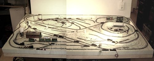
June 4th, 2005: Construction progress of the set
»At this spot (left background) the trains will have the choice to either run down the ramp, reaching normal altitude, or they may travel across a long bridge section, following an 'eight shape', until they also reach normal altitude at the foreground right section. A River-Kwai like bridge will serve as an eye catcher, made of tooth picks, barbecue sticks and some balsa wood. The vertical beams are made of 3 mm shashlik sticks, the larger diagonals were fabricated from 2,5 mm sticks and the horizontal elements are just shortened tooth picks. In all, less than 5 EUR for the material and less than 8 hours of work.«
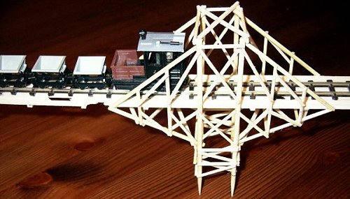
June 17th, 2005: Details of the »River Kwai Bridge«
»In the centre of the set, all the switching activities and the plant traffic will take place. It is possible to remotely decouple EGGER-BAHN cars, but they cannot be pushed in this condition. Therefore, all decoupling sections will be equipped with dedicated locos to push the decoupled train section to their final destinations. Here, engines, having lost their coupling hooks over the time, will be used. By these means they will earn their charity...
The set will be controlled by an Uhlenbrock Intellibox. Control of the switches and the decoupling rails will be made via a home made box, comprising a schematic track layout plus status feedback via bi-colour LEDs.
Maybe much or even too much track within this limited space, but it should be possible to hide a large portion by 'large wooden areas', so that the tracks will not be too dominant. In fact, it is not necessary to see all rails from a single perspective.
I am currently modifying one EGGER engine towards a Video loco so that the whole set can be viewed from the driver's perspective.
Overall 8 engines with corresponding cars are at hand:
2 diesel engines, 2 steam engines, 1 electric engine #3, 1 construction train engine, 1 western steam engine and 1 block steam engine.«

December 28th, 2005: Total view of the »River Kwai Bridge«
»Over the Christmas period, the whole bridge has been completed - my usual stick construction - now with the central Kwai Bridge.
Already during the Advent season the layout for the control centre had been finalised; it will serve as a flat box in A3 format in front of the set. The actual orientation of the switches will be indicated by 3 mm bi-colour LEDs: green for straight and red for turnoff.«
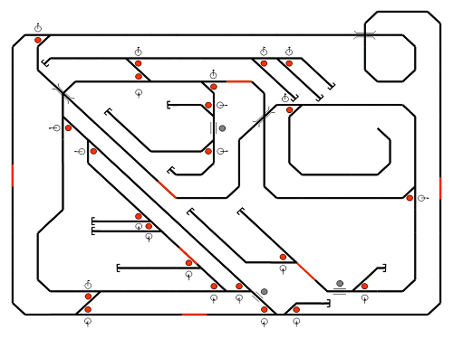
December 28th, 2005: Track layout for the control centre
»Operation is performed by mini toggle switches (ON-OFF-ON) within this A3 diagram (shown here as small circles). Positions of the LEDs are marked by small red dots.
The red track sections are indicating the power supplying spots. The small grey dots are marking the decoupling rails; controlled by mini push buttons.
It was not that easy to get along without using gates, bistatic (=expensive) relais or even TTL- or CMOS-ICs; however it seems that I found another suitable solution:«
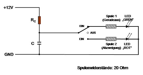
»The idea for switching a track direction is he following:
- The toggle switch is put to OFF for about 1 sec.
- During this time the capacity C (1000 microFarads) will be loaded via the
loading resistor (1,2 kOhms) to a voltage of 12 Volts.
- The toggle switch is pushed to ON, accrding to the desired direction.
- The charge of the capacitor will rush a current pulse through the selected coil
of the switch. The LEDs are easily accepting this peak load.
- Hereafter, a small static current, limited by the coil of the switch, will flow
through the LED; indicating its actual direction.
Each further change of direction will commence at step 1.
This method has been tested and is working remarkably well.«
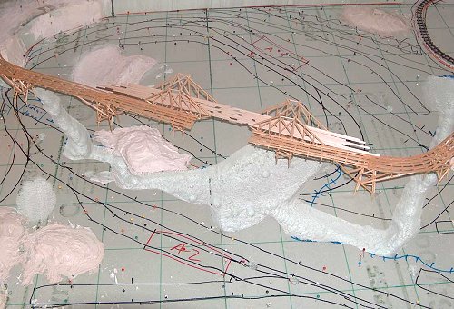
January 3rd, 2006: Starting with landscaping
»Upon completion of the basic landscaping, the colouring of the track sections and the meadow areas was made; just colour so that later gaps of the surface will not show the Styrodur underneath...«
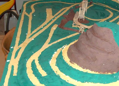
January 4th, 2006: Set with basic colours applied
»Here the preliminarily coloured set; as said, these unrealistic colours will only serve as a primer. The surface will receive a solid grass cover or sand. The brown sections will be lava stones (ground to H0 scale). Finally, my meanwhile demolished mountain Hummerich will come back to life in this set...«
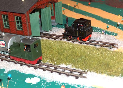
January 4th, 2006: Greening and sanding tests
»These are just excerpts of the meadows to be created with the NOCH Grasmaster. Now, work will proceed!«
To be continued!
So far the comments from Volker Klein. Just visit this site from time to time to see new images, which will be incorporated as soon as I will have received them!